Click on the Images to enlarge to Human Size (800 x ??? pixels wide).
Click on the Text Links for Super Duper Sized! (Dizzamn that's BIG)
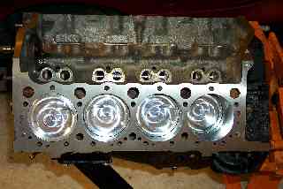
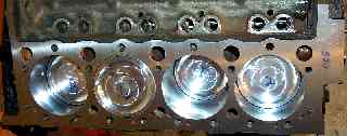
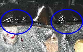
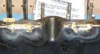
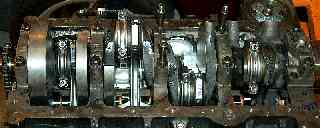
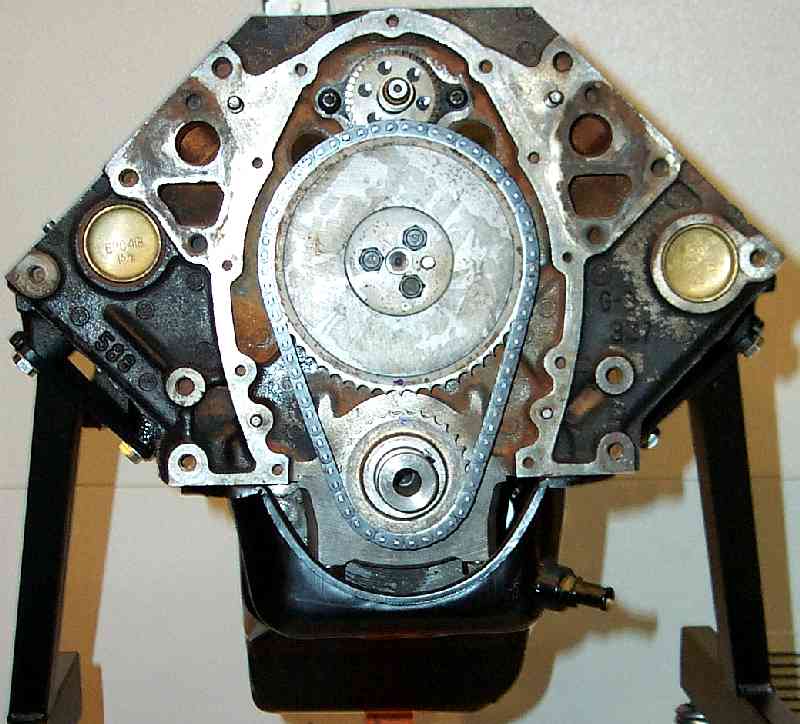
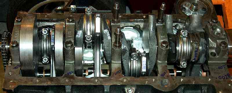
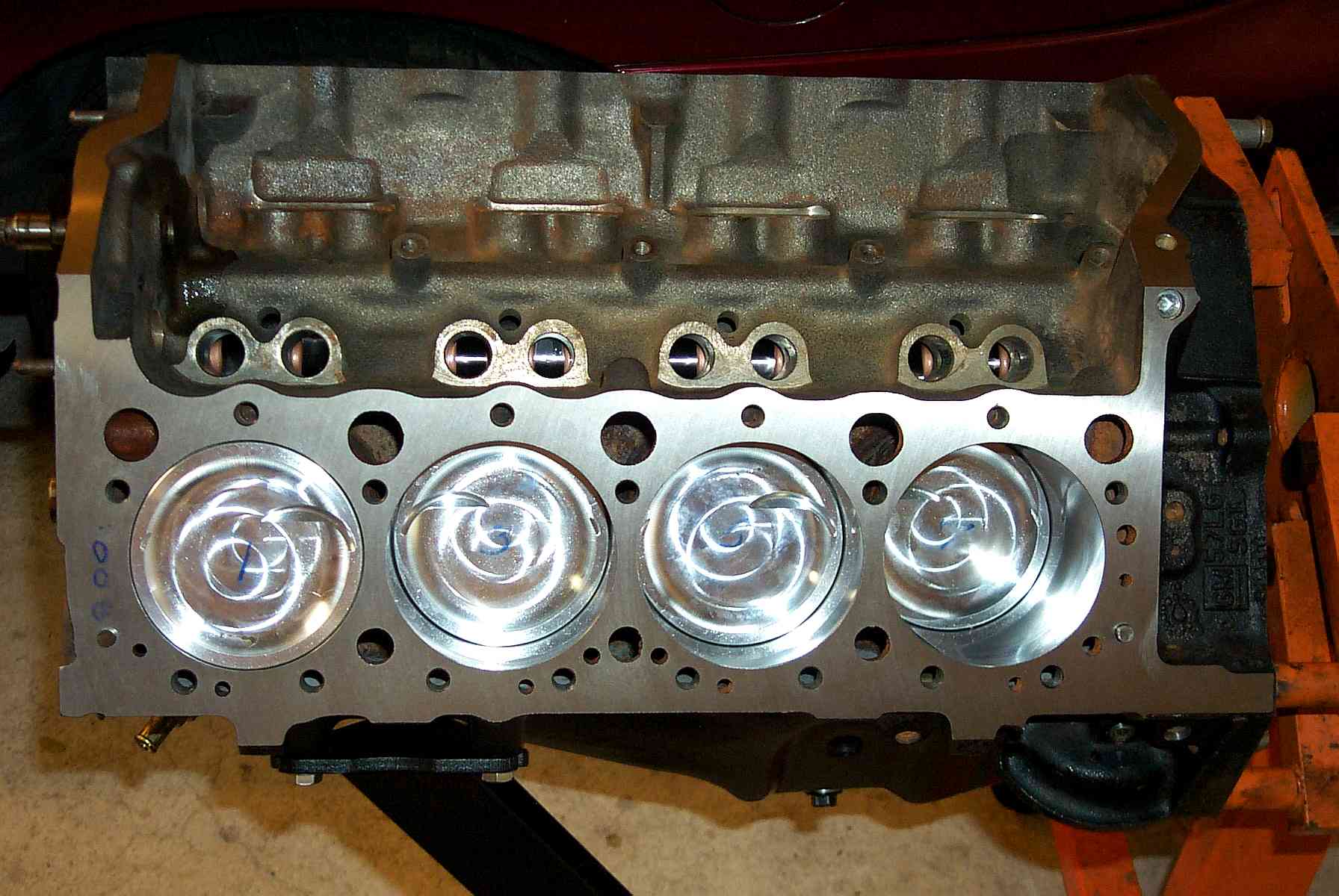
The LH side of the engine.
Notable are the fly cuts in the -31cc JE pistons to clear the intake
and exhaust valves. Look carefully for the small exhaust valve cuts.
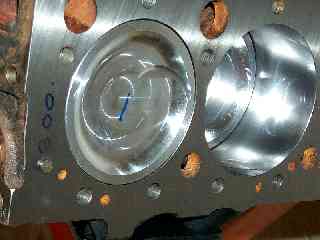
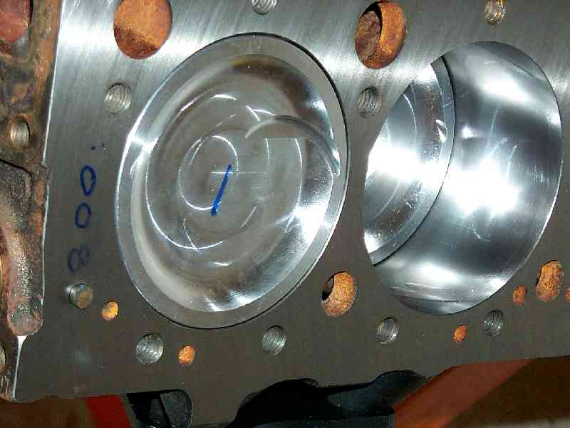
The valve relief flycuts flycuts show nicely here.
Look at #3 for the small exhaust valve cut.
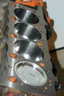
This image shows the cross hatching
in the bores nicely.
The .008" refers to how far down in the hole the pistons are.
Quench is a non-issue with the deep inverse dome pistons.
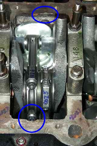
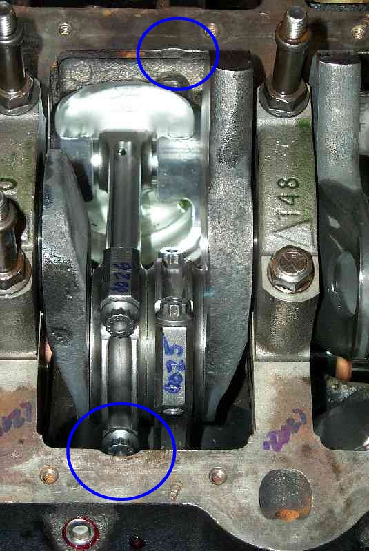
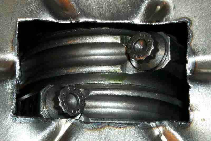
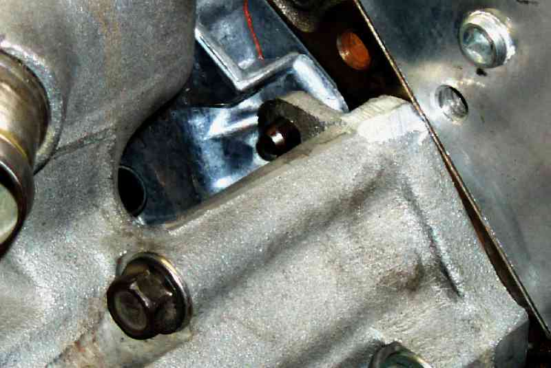
Note the clearance cut into the block
at the pan rail to clear the rod bolts.
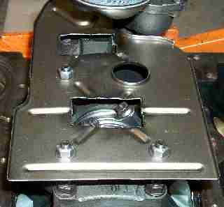
My first problem solved: The rod bolts hit the windage tray.
Thanks to Joe "Plasma Cutter" Gervais, I now have two
holes cut into the windage tray to clearance the rods
I spun the crank to mark the bottom of the tray
where it needed to be cut. Plasma cutters are used in
muffler shops everywhere. Bring a six pack and get the
holes cut at your local shop. A cutoff wheel will work
in a pinch, but it would suck to do it that way. Clean
the tray carefully with a wire brush and a bastard file.
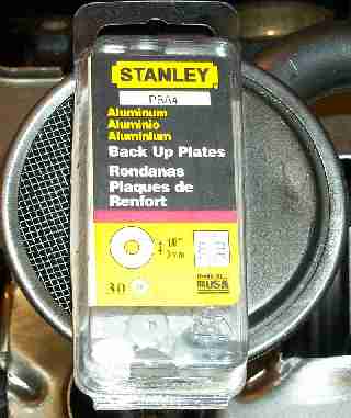
I used one of these to shim the spring in the oil pump. They are
.060" inch thick and the pump gives me ~70PSI at redline now.
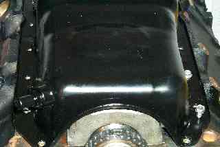
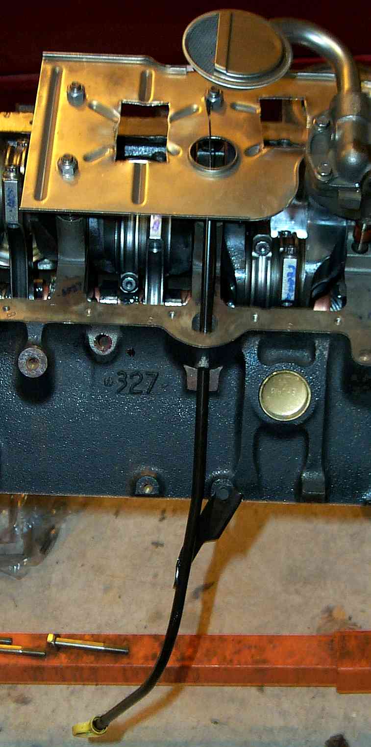
The RH side of the engine
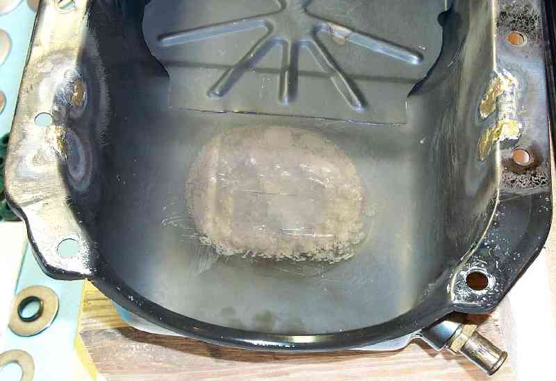
This is a serious problem solver - what to do for an oil pan.
The stock pan won't work due to the rod bolts hitting it. Normally people
have been buying aftermarket pans from Canton, etc. I elected not to do that.
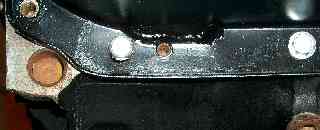
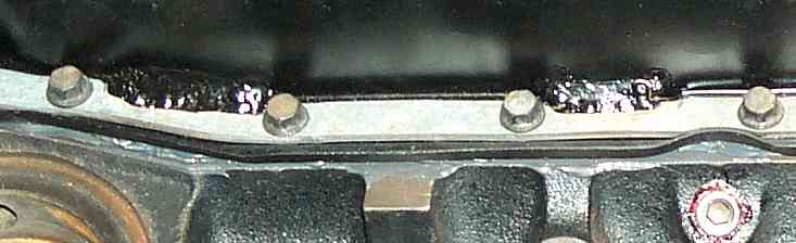
This is a close up of the modified stock oil pan. Aftermarket LT1 oil pans
are a pain fitment wise. They tend to hit the steering rack (Canton) or
have problems with oil sloshing off the pick up in the corners, or have
problems with the oil level idiot light sensor or... You get the idea.
I also have a Vortech blower oil return fitting welded onto my stock pan.
I could have not only paid for a new pan and dealt with the fitment headaches,
but I'd also have to buy a new oil return fitting and have that welded onto it.
That's all too rich for my wallet and too many problems for my tastes, so a
modified stock pan will have to do. Mike had one of the guys in the shop
work the pan with a BFH, a tig welder and some brazing until it all fit. It's
not pretty, but it's functional, cheaper and a lot less headache this way.

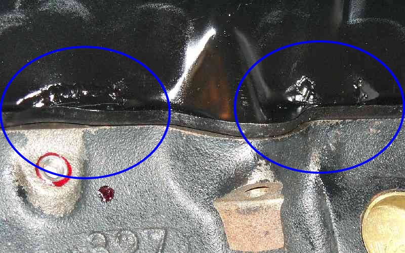
The pan was slit near the rail, the resulting "flaps"
pushed out and the gaps tig welded and brazed to seal them.
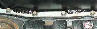
Sadly, every solution has it's price.
Notice how the
pushed out pan will interfer with the bolt next to #2. Lots
of goo will have to go here to seal the pan in this area.
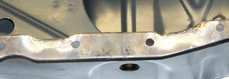
I also had to grind clearance into the pan support rails on both.
sides of the engine to clearance the kick outs. I also had to grind
down (flat side) some washers on a few of the bolts to get good clamp-
ing force down to the pan support rails. It's a bit ugly but it works ok.
Late note: After installing the engine, I discovered 3 of the brazes
had pin holes allowing oil to leak from the pan. I should have sealed
the brazes with a layer of JB Weld before putting the pan rails on. On
one of the brazes I did put a layer of RTV over it, and that isn't leaking.
The rest I ignored. Lesson Learned is to JB Weld seal all the brazes on
the outside of the pan prior to putting the pan support rails on.
OMG it's a DOG!!!.
Check out the Stoopid Puppy Pix Page!
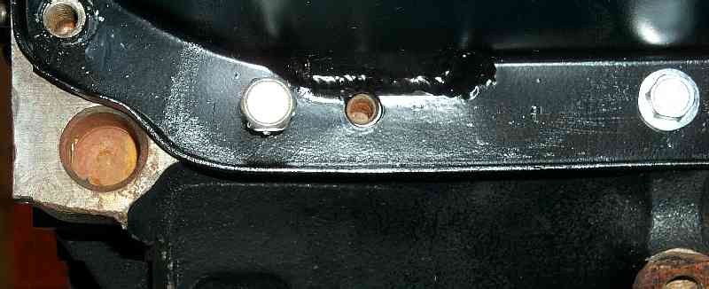
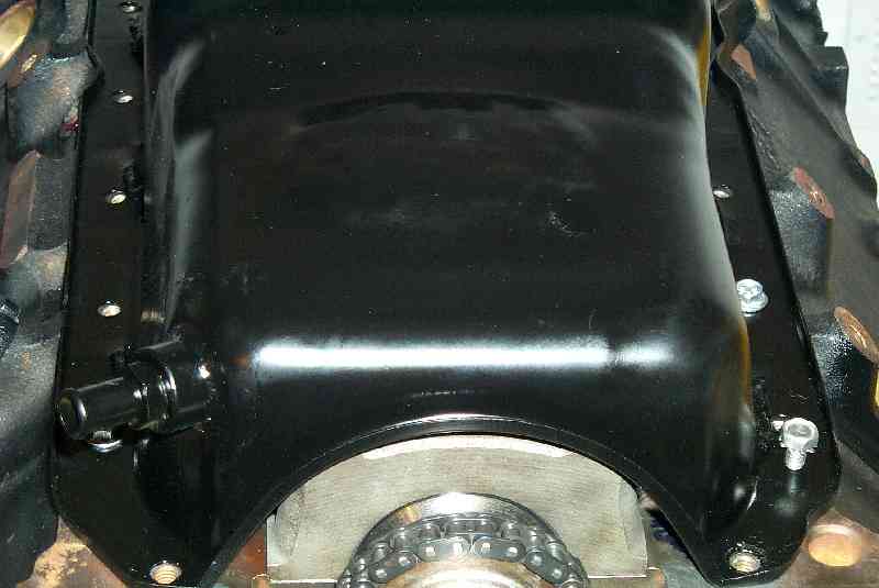
This photo shows where the bottom of the pan was
"calibrated" by a BFH to clear
the stroker crank.
Also visible is the Vortech oil return fitting on the left.
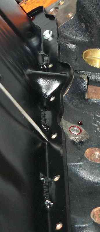
Detail of the work done on the
pan rail to clear the stroker crank.
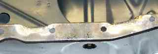
Another view of the pan rail to clear
the crank.<
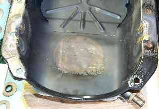
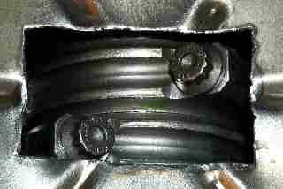
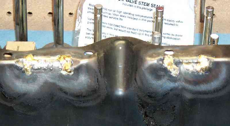
Inside view of the work done to clear
the stroker
crank. Keep your BFH and a torch handy...
Glory shot of rotating assembly.

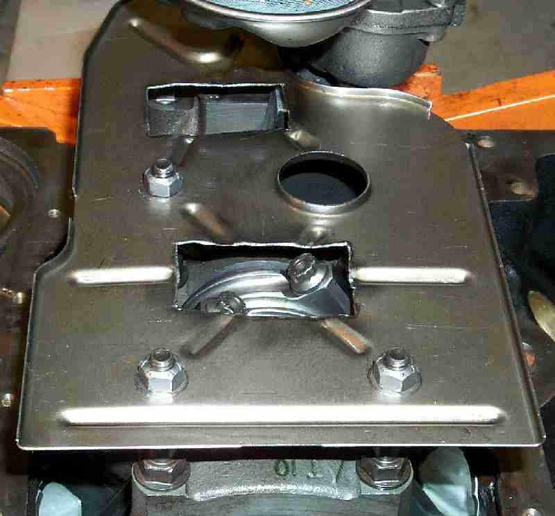
The dipstick has been a real PIA for me in the past. It's hard
to remove from the engine while it's in the car, and often hits the
crank when after market oil pans are used.
I haven't seen this particular image before and it's very helpful
indeed to see how it is kept away from the crank by the hole in
the windage tray. This is a brand new dipstick tube btw, my old
one was hacked up eons ago when the headers went on.
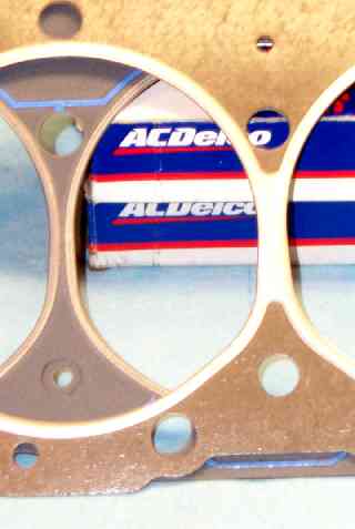
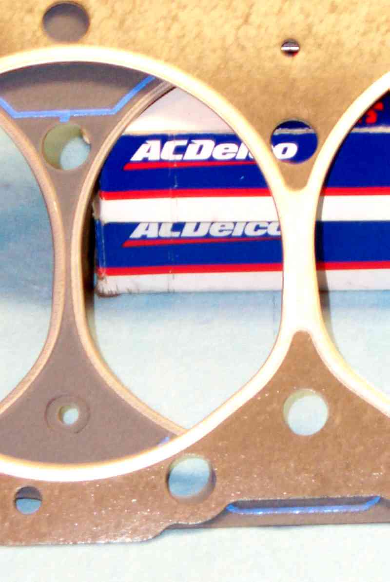
The bottom gasket is the FelPro p/n 9999 gasket, the upper
one is the stock gasket. Note the coolant holes are different
sizes. After reading the FelPro directions and asking the F-buds.
I installed the FelPro's unmodified.
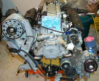
I did a pre-install mockup build of the long block just
to ensure everything was going to be ok. I found only
one "gotchya" (see next image).
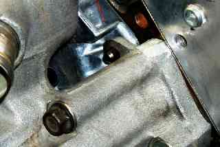
Since both the heads and the block have been decked, I had to
grind some flash off the waterpump to clearance the Vortech bracket
that mounts to the LH head. Everything else went back on smoothly
Back to Index


